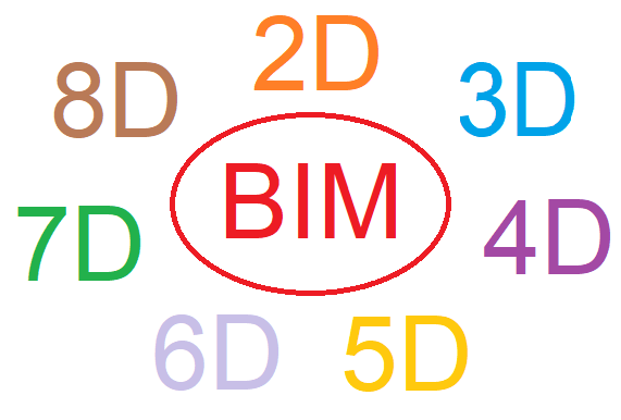
BIM – Building Information Modeling – is a process that involves creating and using an intelligent 3D model to inform and communicate project decisions. It has various components:
- 2D 2-Dimensional view
- 3D 3-Dimensional Model
- 4D + Time Schedule
- 5D + Budget (Cost)
- 6D + Facilities management (Maintenance)
- 7D + Sustainability (Life Cycle)
- 8D + Occupational safety and health
1. BIM
Building Information Modeling (BIM) is a digital representation of physical and functional characteristics of a facility. A BIM is a shared knowledge resource for information about a facility forming a reliable basis for decisions during its life-cycle; defined as existing from earliest conception to demolition.
2. BIM software
Building Information Modeling (BIM) is an intelligent 3D model-based process that gives architecture, engineering, and construction (AEC) professionals the insight and tools to more efficiently plan, design, construct, and manage buildings and infrastructure.
3. 3D BIM – The shared information model
3D BIM is the process of creating graphical and non-graphical information and sharing this information in a Common Data Environment (CDE). This refers to traditional 3D Model what we are creating and CAD Software.
Benefits
- Improved visualization of the project, communication of design intent
- Improved multidisciplinary collaboration
- Reduced rework
4. 4D BIM – Construction sequencing
4D = 3D + TIME SCHEDULE
4D BIM adds an extra dimension of information to a project information model in the form of scheduling data. This data is added to components which will build in detail as the project progresses. This information can be used to obtain accurate programme information and visualisations showing how your project will develop sequentially.
Activity Planning in 4D, 4D Scheduling / Construction Sequencing. … These animated models represent the planned construction sequence set against time. The main purpose of a construction phasing simulation is to provide a tool that will help the construction team visualize logistical issues or inefficiencies.
Benefits
Integrating BIM with 4D CAD simulation models bring benefits to participants in terms of planning optimization.
Builders and manufacturers can optimize their construction activities and team coordination.
5. 5D BIM – Cost
5D = 3D + TIME SCHEDULE + COST.
5D BIM, an acronym for 5-dimensional building information modelling, is a term used in the CAD and construction industries, and refers to the intelligent linking of individual 3D CAD components or assemblies with time schedule (4D BIM) constraints and then with cost-related information.
Drawing on the components of the information model being able to extract accurate cost information is what’s at the heart of 5D BIM.
Project Management in 5D, Project controlling in 5D In 5D schedules and costs are linked to the 3D models.
Benefits
Integrating BIM with 5D CAD simulation models enables the development of more efficient, cost-effective and sustainable constructions.
6. 6D BIM – Project lifecycle information
6D = 3D + TIME SCHEDULE + COST + INTELLEGENT LINKING
Operations and Maintenance in 6D and
6D BIM stands for 6D Building Information Modeling. It is a phrase extensively used in the AEC industry and refers to the intellectual linking of all the individual 3D CAD components or assemblies with all aspects of project life-cycle management information
Benefits
Integrating BIM with 6D CAD simulation models leads to an overall reduction in energy consumption.
7. 7D BIM – Sustainability
7D = 3D + TIME SCHEDULE + COST + INTELLEGENT LINKING + SUSTAINABILITY
7D–BIM (seventh-dimensional building information modelling) is used by managers in the operation and maintenance of the facility throughout its life cycle. … Integrating BIM with 7D CAD simulation models optimizes asset management from design to demolition.
Benefits
Integrating BIM with 7D CAD simulation models optimizes asset management from design to demolition.
8. 8D BIM – Prevention through Design (PtD)
8D = 3D + TIME SCHEDULE + COST + INTELLEGENT LINKING + SUSTAINABILITY + PREVENTION
8D BIM Modelling Tool For Accident Prevention Through Design
But until now the tools for effectively managing the links between design and safety on site have not been available. Building information modelling (BIM) is an emerging paradigm in the design and engineering field.
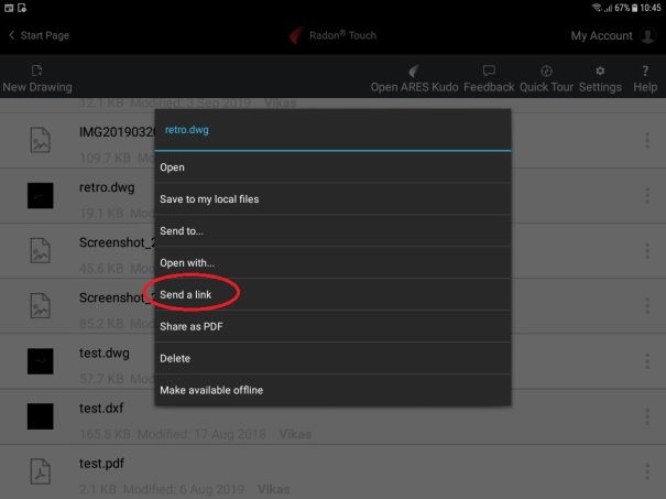
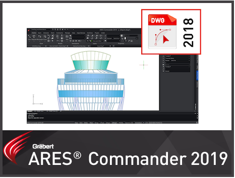
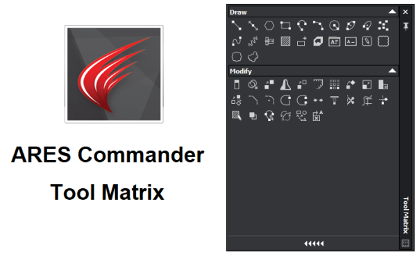
Now ARES Commander 2020 has BIM capabilities.
– In ARES Commander 2020 you can work with BIM files
- Import IFC or Revit® files in your project
- BIM Navigator palette
- Data Extraction for BIM Elements
-
BIM Elements Properties
-
BIM Model Sections
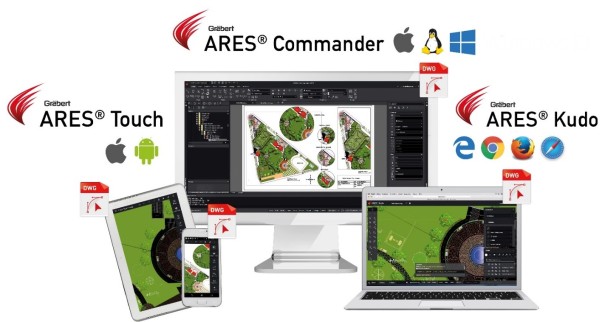
Download latest version of ARES Commander today and experience it.
https://www.graebert.com/cad-software/download/
ARES Commander is a product from Graebert GmbH. Graebert GmbH is a leading developer of custom CAD software, solutions and services and has over 30 years of technology expertise…
Disclaimer: I work for Graebert GmbH and occasionally write for CAD -Tips and Tricks.
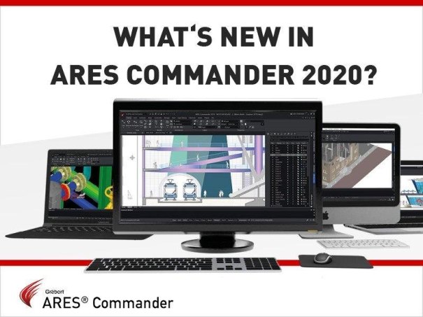
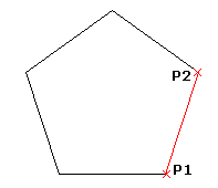
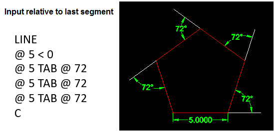
 Today I will tell you something about Megagon. A Megagon is a Polygon with 1 Million Sides.
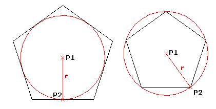


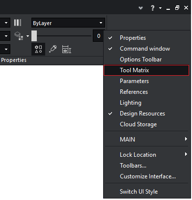
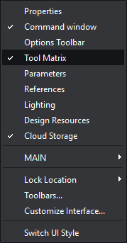
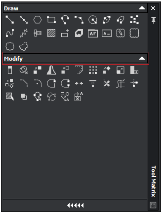
 and drag the toolbar onto the Tool Matrix.
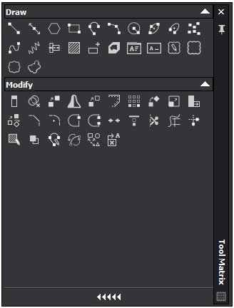
 on the toolbar.
 on the toolbar.
 on the Tool Matrix.
 on the Tool Matrix.